
Heat-treatment
- Pre-heating
- Post-heating
- PWHT
- General for Heat-treatment
- Electric Resistance Heat-treatment
- Gas Combution type Heat-treatment
- Harness Measurement
- Vessel Service
- Plant Service
◎ Pre-heating
Pre-Heating is, as a subsidiary process of welding work, before and during welding, the operation of heating the part of the base metal on which welding metal is melted and attached. The fundamental purpose of putting in operation of Pre-Heating is to prevent from cracking at Welding zone and the Heat affected zone The effects of Pre-Heating when welding are as below 1) Make heat loss decrease so that the hardness level of the material can decrease by slowing the cooling velocity of welding part. 2) Repress one-side sitting of impurities can make cracking. 3) Make thermal transforming volume by welding decrease. 4) Make easy to emission of hydrogen and repress the happening of the crack by hydrogen.. 5) By eliminating water on the base metal on which welding metal is melted and attached, make welding metal prevent from incoming hydrogen in the welding metal. 6) Make easy for welding metal to melt and attach.
◎ Interpass Temperature
There is Interpass Temperature related to Pre-Heating. The welding part completed through Multi-Pass is affected by the remaining heat of the last pass. Interpass Temperature is the temperature of base metal at welding part heated by the welding heat of the last Pass, just before the Multi-Pass welding raises Arc. If Interpass Temperature is beyond 200℃, hardness and impact value may drop, and for stainless steel it happen to raise Weld Decay. So Interpass Temperature should be below the appropriate temperature. So, Interpass Temperature is presented as maximum temperature, however, always minimum Pre-Heating temperature should be kept as well, and this should be applied when temporary welding of assemply cast, maintenance welding and Gouging as same as the conditions of main welding.
◎ Post-heating
Post-heating is the operation maintaining a certain amount of time with a certain consistant temperature after fishing welding. For this job, the terms is used, not unified as Treatment after welding, Heat after welding abd etc., but it should be classified from PWHT. There is no standard, code on this, but as a similar concept, there is the case that delaying PWHT, not putting in operation after welding on ASME B31.1, B31.3, or when stoping welding, there is the case of intermediate Heat Treatment properly on the welding part with the properly controlled cooling speed, or there is the case that requires to use other appropriate method. Post-Heating is mainly used for the purpose of removing the remaining hydrogen in melted and attacged metal, and low temperature after welding method that is after welding completion, the heating with 100~200℃ temperature range for 1 ~ 5 hours, is effective. Also, when welding the Pressure Vessel, there is the case that requires to heat afterwards with Pre-Heating Temp. + (100℃ - 200℃) range, or Pre-Heating Temp. + (120℃ - 150℃) range for 1-2 hours. Basically, as for the temperature and the time of the Heating after welding, the Engineering should be determined by WPS and WPQ per material and thickness, and there is the case sometimes that requires to heat after welding together with Pre-Heating on fabricating of a certain Pressure vessel type in Korea.
◎ PWHT
PWHT is, to improve the performance of the welding part and to eliminate the harmful effect of the remaining stress, under the temperature below the transformation zone of the metal, heating equally the welding part and Heat affected zone with a regular speed and maintaing a certain amount of time, and then cooling equally with a regular spped. The effect of PWHT is as below; 1. Relief of welding remaining stress 2. Stabilization of feature and dimensions(for machinery processing) 3. Softening of Heat affected zone 4. Increase of softness of welding metal 5. Improvement of destruction-resistance ratio 6. Removal of containing Gas 7. Improvement of CREEP characteristics 8. Improvement of capability agiant corrosion 9. Improvement of fatigue strength degree
◎ Necessary conditions for Heat-treatment
The following chart should be determined to precise Pre-Heating and PWHT. If the contents are not stipulated in the applied standard, apply a stipulation of other standard, or discuss with the constructioner to make out WPS, and will apply to actual construction after confirming the effectiveness by WPQ.
| Items | Pre-heating(Pipe and VESSEL) | PWHT(Pipe and VESSEL) |
|---|---|---|
| 1. LOADING/UNLOADING Temperature | O | O |
| 2. Heating Speed(MAX., MIN.) | O | O |
| 3. Heating Method | △ | △ |
| 4. Permitted Temp. difference when heating | △ | O |
| 5. Maintaining Temp.(MAX., MIN) | O | O |
| 6. Maintaining Time(MAX., MIN) | X | O |
| 7. The temp. between PASS(MAX.) | O | X |
| 8. Heating speed to PWHT Temp. | O | X |
| 9. PW HT Temp.(MAX., MIN) | O | X |
| 10. Maintaining Temp. at PWHT Temp.(MAX., MIN) | O | X |
| 11. Cooling speed(MAX., MIN) | O | O |
| 12. Cooling method | △ | △ |
| 13. Permitted Temp, difference when cooling | △ | O |
| 14. Number of attachment and location of T.C | O | O |
| 15. T.C attachment method | O | O |
| 16. The range of Pre-Heating/ Heat treatment | △ | △ |
| 17. The width of Heating | △ | △ |
| 18. The range of keeping warm | △ | △ |
| 19. The type of keeping warm material | △ | △ |
| 20. The method of keeping warm and thickness | △ | △ |
| 21. Temp. incline of each part (when heating, maintaining, cooling) | △ | △ |
[Symbol]
○ : always stipulated.
△ : may not stipulated.
ⅹ : usually not stipulated.
[Remarks] Since “usually not stipulated “ is sometimes stipulated, it should confirm if it should be stipulated or not with client.
◎ General for Heat-treatment
△ Measurement of Temperature
Measurement of Temperature is putting in operation for the record of temperature and management of temperature during Heat Treatment to do quality guarantee for Heat Treatment. Measurement of Temperature is, putting into practice using T.C. by connecting a Compensation Wire to make a circuit with Temperature Recorder, measuring the temperature of the surface of the part to be measured, and at the same time recording the temperature. Thermocouple is the thing made a circuit with two different metal wire. If the two contact points maintain two different temperature, a Heat Electromotive Force corresponding to the difference of temperature arises to flow a current. Since there is the regular relation between the Heat Electromotive Forcer and the temperature, by measuring this Electromotive Force the temperature can be measured. Compensation Wire is putting an insulation on one pair of wire those charateristics of the Heat Electromove Force is similar to the charateristic of T.C, and instead of T.C. using contacting between the terminal and the Temperature recoder, compensate the difference of temperature of the terminal part.
△ Thermocouple
The selection of T.C. is made by selecting the type, dimension and etc. according to the temperature range to measure. There is the case that they use the Sheath with outer diameter 3.2mm among the Sheath T.C. laying K-Type 0.75% rating in stainless steel protection tube, but especially, recently, to do more precise temperature measurement, the consuming type T.C. insulated with Glass Fiber at 0.65mm ranged T.C. wire is welded to the part to be measured to measure the temperature.
△ Compensation Wire
In case of measuring temperature with the T.C., it is desirable that the T.C. contacts measuring gauge directly, In reality, there is a problem with a distance, and the problem of drop of accuracy happens due to a electromagnetic induction and other disturbance. Therefore, with the thing which put an insulation and protection clothing on a pair of 2 types conductors having the Heat Electromotive Force characteristics as same as or very similar to the Heat Electromotive Force characteristics of the T.C., that is, with Compensation Wire, by connecting the T.C. and the measuring unit, compensates the temperature of the contact point with the same effect of extension of the T.C., besides, protects various disturbances in the path and then enables to do the precise measurement of the temperature. Therefore, appropriate selection method, using method should be adapted. As for K-TYPE T.C. the Compensation Wire of VX-TYPE or KX-TYPE should be used.
△ Welding method of T.C
Welding Method of T.C is followings; But, according to the type of T.C. welder, charging and discharging method may be a little different. ① Remove the scale at the part for T.C. and Earth. ② Charge TAU (Portable T.C. welder, Thermocouple Attachment Unit) at night. ③ Attach the magnetic of TAU. to the pipe to be a earth, hold T.C. with Radio Pinchers and locate the head of T.C. wire to the part to attach. ④ by pressing Charge Button, confirm the charge to Voltage gauge or Lamp, and then by pressing Discharge Button, make spark. ⑤ Weld T.C. each one open part , let the clearance between the two polar of T.C. be within 6mm. ⑥ Insulate the contact point by covering Putty used for high temperature.
△ Temperature Recorder
With Multi-point type automatic Temperature Recorder, measure and record temperature during doing PWHT for the part to be measured. Temperature Recorder is an electronic type and there are many types. It is important to select one fit to T.C. and Compensation Wire. For example, in case of using K-TYPE, input of temperature recorder should be set as K-TYPE T.C . Automatic Temperature Recorder is to put in operation a regular calibration test, and to put into practice maintenance inspection within the permitted error range in accordance with the standard.
△ Keeping warm and Insulation of
1) Classification by material
| Type | Content |
|---|---|
| Glass material Keeping warm material | Glass Fiber, Foam Glass |
| Mineral material Keeping warm material | Fiber feature : Asbestos, Rock-Wool, Slag-Wool Multi-cavity feature : Pearlite, Vermiculite |
| Castable Fire-resistant keeping warm material | Multi-cavity material , Chamotte or Multi-cavity Clay material , High Alumina material |
| Fire-resistant keeping warm material for high temperature | Silicic matenal, Quartz Glass material, Alumina material, Zirconia material |
| Carbon material Keeping warm material | Carbon material Fiber, Carbon Powder |
2) Classification by feature
| Type | Content |
|---|---|
| Fiber feature keeping warm material | Glass Fiber, Asbestos, Rock-Wool, Ceramic Fiber |
| Multi-Cavity feature Keeping warm material | Synthetic Resin Foam material, Brick |
| Air layer Keeping warm material | Air layer interposed Aluminium, Paper, Plastic |
3) Classification by Chemical property
| Type | Content |
|---|---|
| Acidic Keeping warm material | The material which main component is SiO2 |
| Alkalic Keeping warm material | The material which main component is CaO, MgO |
| Neutral Keeping warm material | The material which main component is AI2O3, Cr2O3, Fe2O3 |
The following items are required as the conditions of Keeping warm material (1) As the electrical point of view, The insulation degree should be high. (2) As the economical point of view, it should have the physical strength to use repeatedly. (3) Since directly contacts Heater or pipe, it should chemically be stabilized. (4) It should have the strength between heat, and have high keeping warm & insulation of heat effectiveness.
△ Keeping Warm Construction
The keeping warm material and keeping warm construction thickness normally used are as below
| Type | Electric Pre-Heating | Electric PWHT | Gas Firing PWHT |
|---|---|---|---|
| Ceramic Fiber(over 1000℃ heat -resistance) | 25mm | 50mm | 50mm |
| Rock-Wool (Mineral Wool) | - | - | 75mm |
Note. When constructing Gas Firing PWHT, considering economical point, Mineral Wool is used as a keeping warm material, but, Ceramic Fiber is used to consruct the part which is hard to construct.
The standard list related to PWHT
The standard to regulate the related to PWHT are as followings (1) ASME BPV Code Sec.Ⅰ, Power Boilers (2) ASME BPV Code Sec. Ⅲ, Rule for Construction of Nuclear Power Plant Components 중 Subsec. NB, NC, ND, NE, NF, NG 4600 (3) ASME BPV Code Sec. Ⅷ, Rules for Construction of Pressure Vessels Div. 1, Div. 3. (4) ASME BPV Code Sec. Ⅸ, Welding and Brazing Qualifications (5) ASME B31.1, Power Piping (6) ASME B31.3, Process Piping (7) JIS Z3700, The method of PWHT for Pressure Vessel (8) ANSI/AWS D1.1, Structural Welding Code (9) BS 5500, Specification for Unfired Fusion Welded Pressure Vessels (10)BS 1113, Specification for Design and Manufacture of Water-Tube Steam Generating Plant (Including Super-Heaters, Reheaters and Steel Tube) (11) BS 1515 - After1987, unified to BS 5500. (12) BS 2633, Specification for Class 1 Arc Welding of Ferritic Steel Pipework for Carrying Fluids (13) API 620, Design and Construction of Large, Welded Low-Pressure Storage Tanks (14) API 650, Welded Steel Tanks for Oil Storage (15) Korea Electric Power Industry Code (KEPIC), Nuclear machinary (MNA,MNB,MNC,MND,MNE,MNF,MNG,MNZ), Pressure Vessel(MGB), Heat Exchanger(MGC), Storage Tank(MGD), Pipe(MGE), Valve (MGG), Boiler (MBB) and others (16) Japan, HPIS E107 ( Japan High Pressure Technology Association Standard) (17) Japan, Pressure Vessel Structure Standard (18) Japan, Generation Facilities Welding Technology Basis in Electricity Business Regulations (19) Japan, Specific Facilities Inspection Regulations in High Pressure Gas Handling Method (20) Korea, Specific Facilities Removing Stress Basis in High Pressure Gas Safety Control Regulations
◎ Electric Resistance Heat-treatment
△ Summary of the heating method
Electric Resistance Heating is commonly named as the heating the treated material using the Joule Heat generated when a current flows to a electric resistant material, and is classified as 3 types as the Conduct Heating type, the Convection Heating type and the Radiation Heating type by the heat transfer form. Electric resistant material is used as the flexible Ni-Cr type, Fe-Cr type and etc., that is the metal material having a high electric resistant value. And it is used to fabricating Heater with various forms as per the usage such as Rope form, Velt form, Mat form. Channel(or Box) form and etc.. Generally many using one is the Conduct Heating type heating the heated material to which the Heater is directly contacted, and especially for the Heat Treatment for Pipe this form is mostly used. Described below are the Electric Resistance Heat Treatment by the Conduct Heating form.
△ Component units and Control
Electric Resistance type Heating consists of the following units. (1) Programmable Controller (P.C) (2) Temperature Indicator Controller (T.I.C) (3) Power Regulating Unit (4) Heater (5) Temperature Recorder (6) T.C for Control and for Record
The units used and the connections between the units are as below;
△ Confirmation of the treated material
1. The initial status of the heat treated material
(1) The location of Heat Treatment of the Heat treated material
(2) Material, feature, diameter of the pipe, thickness
(3) The history of Heat Treatment
(4) Confirming if the execution of defect inspection in advance or not.
(5) Confirming if there is a defect, a transformation or not by visual inspection before Heat Treatment .
(6) The inspection for the support method and support status of the heat treated material
(7) Check and record if there is a transformation before Heat Treatment for the material having a possible transformation.
(8) Confirmation and removal if there is the parts such as Gasket, Valve,and etc. of the pipe that would be damaged
when heating.
2. Heat Expansion
If the expansion is restricted, transformation, damage and etc happens. So confirm if it can be expanded freely over the expansion rate. If necessary. after confirming the length of the heating part, the average line expansion value of the material and the expansion rate of length/diameter direction according to the heating temperature, manage as below; (1) In case of pipe, remove Flange Bolt and Gasket around the part of Heat Treatment. (2) Relax U-Bolt for fixing pipe, Remove other fixing unit. (3) Relax and remove the restricting material against free expansion. (4) If necessary, install expansion unit that make easy to expand such as the Sliding Plate, the Roller Unit and etc..
3. Study on the possibility of transformation of the Heat treated material
As for the transformation of the Heat treated material, hard to explain simply, however mainly it happens in case of the lack of strengh against high temperature of the Heat treated material and there is a transformation by a inner remaining force. (1) The transformation due to Heat expansion (2) The transformation due to the lack of strengh against high temperature (3) The transformation by the Inner Remaining Stress
△ Confirmation of Heat-treatment Specifications
Confirm the Heat Treatment Specifictions including the followings (1) The method of Heat Treatment and the scope of removal of the Stress (2) Loading Temperature (3) Heating speed (4) Maintaining temperature maintaining time (5) Cooling speed (6) Unloading Temperature (7) Temperature difference when Heating and Cooling (8) Temperature difference when maintaining (9) Required temperature decline per other sites (10) Heating range (11) Keeping warm range (12) The location and the number of T.C (13) If the Hardness Test or not and the issue related to other inspection after Heat Treatment (14) The limit time of Heat Treatment
△ The installation and the wiring of Heater and T.C
1. The selection of Heater
Determine the Heater to use and the number of Heater after considering the followings. (1) The number of Control Zone (2) Wiring method of the Heater (3) Maximum expected the Required Heat Volume and the configuration of the Heater (4) The number of using unit
2. installation and keeping warm of the Heater
After determining the Heater to use and the number of usage, install the Heater on the Heat treated material. Typical installation and the Keeping warm method of the Heater are as below drawing.
3. The welding of T.C
After installing the Heater, before the Keeping warm or if necessary, before installing the Heater, weld T.C. with the Storage Electricity Discharge type T.C. welder. T.C is commonly used as the K-Type Wire T.C, and the Compensation Wire is used as the VX Type.
△ Installation and Keeping Warm of the Heater
△ Installation of the Heater and a Cross Sectional View for Keeping Warm
△ Inspection before Heat-treatment
Before starting Heat Treatment, inspect the following issues. (1) Inspect the installation of the Heater and the status of Keeping warm. (2) Input and confirm the Heat Treatment Curve in Programmable Controller. (3) Inspect the wiring of each Power source, Control Electric source. (4) Confirm the wiring of T.C. (5) Confirm each calibration of the Temp. Recorder, T.I.C, and P.C. Use Cal-Checker. (6) Confirm the remaining recording paer of the Temp. Recorder. (7) Put the power on and confirm the following issues and if there is abnormal repair it. * Put the control power source on and confirm the operation status of the units such as the Temp. Recorder, T.I.C, P.C, Power Unit and etc.. * Confirm if each T.C is abnormal or not. (Especially, Short, the polarity connection status and etc.) * Put the main Power on, and confirm if there is abnormal on wiring or not and if there is a heat or not. * This inspection should be done below the Loading temperature. (8) When the client requires, take the client’s confirmation as per the necessary stage, such as, after installing the T.C., after installing the Heater, after completion of Keeping warm, and etc..
△ Putting in Operation of Heat-treatment
(1) Adjust the location of the record to be recorded on the new page of the Temp. Recoder. (2) Put the power on. (3) If the difference below the Loading Temp. is too large, stop the processing of P.C. Program below the Loading temp, and, after confirming the difference is within the temp. difference when heating, proceed to the processing of Program again. (4) While confirming the difference is within the required temp. difference when heating, proceed to heating the material with thespeed within the required heating speed. (5) Just before reaching at the maintaining temp.,confirm the temp. difference of the material is within the required difference when maintaining, and, if the difference is large, stop the processing of P.C. Program and after confirming the difference is within the required difference when maintaining temp, enter into the maintaining temperature. (6) If the lowest temperature of the T.C’s becomes to reach the maintaining temperature range, this means reaching the maintaining status. (7) While Confirming the difference within the required temp. difference when maintaining, maintain the (actual) maintaining time over the maintaining time range. (8) After maintaining the maintaining time, put in operation Cooling to the Unloading temp.. When Cooling, cooling speed should be in accordance with the required cooling speed and should be within the required temp. difference of Cooling. (9) If all T.C’s become below Unloading Temp., turn the Power off and finish Heat Treatment.
△ Inspection and Test after Heat-treatment
After Heat Treatment, recover the chart paper of theTemperature Recorder and put in operaion of Inspection in accordance with the contract terms. (1) Study of the chart paper for Heat Treatment and make out the Heat Treatment Record Document. (2) Put in operation of the Hardness Test. (3) Submit the Test and the Inspection Report to the client in accordance with the contract terms.
◎ Gas Combustion Type Heat-treatment
△ Summary
The Gas Combustion System consists of the Gas Primary Supply Unit, the Gas Secondary Supply Unit, the Gas Burner and the Combustion Air Supply Unit. 1. The Gas Primary Supply Unit The Gas Primary Supply Unit consists of the Fuel Gas Supply the Source and the Vaporizer Unit equipped with the Gas Primary Regulator. (1) The Fuel Gas Supply Source can be used as the Gas Tank Lorry, the Gas Gathering Unit or the Gas Source in the plant. (2) The Vaporizer Unit equipped with the Gas Primary Regulator has the role of vaporizing the Liquefied Gas supplied from the Tank Lorry. 2. The Gas Secondary Supply Unit The Gas Secondary Supply Unit consists of the Gas Secondary Regulator, the Fire Watching Unit and the Gas Train Unit, the Gas Controller Unit, the Gas Burner and the Combustion Air Supply Unit .
2. The Gas Secondary Supply Unit The Gas Secondary Supply Unit consists of the Gas Secondary Regulator, the Fire Watching Unit and the Gas Train Unit, the Gas Controller Unit, the Gas Burner and the Combustion Air Supply Unit
△ System Composition
The representative System Composition Diagram is as below
◎ Hardness Measurement
△ The Summary of Hardness Measurement
Hardness Measurement is, after finishing PWHT, the confirming how much the hardness of the Heat treated material becomes. As the measuring tool of hardness, there is the Hardness tester(Hardness gauge) as Vickers, Rockwell, Brinell, Equo-Tip and etc.. On site, portable Brinell or Equo-Tip Hardness gauge is generally used. These forms are all measuring methods by measuring the size of the mark, or repulsion force(repulsion rate) arised by putting a regular weight with Diamond weight, or steel ball on the surface the metal(the Heat treated material). The former(the size of the mark) will have an error according to the strength and the weakness of the hit force and the latter(repulsion force) will have an error according to flatness & smoothness of the finish for the surface. So, each one has a merit and a disadvantage.
△ The Sequence of Hardness Measurement
The sequence of Hardness Measurement is as below (1) Make the surface to be measured flat and smooth with grinding tool as metal Brush, File, Grinder and etc.. (2) Measure the hardness. (3) Convert the hardness value into the usual hardness value (Brinell, Vickers, Rockwell) by using the conversion chart. (4) For the detailed hardness measurement method, refer to the related manual.
△ The part the location and the number of time for Hardness Measurement
The part for Hardness Measurement , the number of measurement point, and the number of time of measurement per one measurement point should be determined through the discussion with the client in advance.
 In case there is no terms and instructions on this in the contract, do as below;
(1) The part to measure is as shown in the right drawing;
① Central part of welding Bead
② Boundary part between welding Bead and base metal
(When the client requires.)
③ Heat Affected Zone of base metal
In case there is no terms and instructions on this in the contract, do as below;
(1) The part to measure is as shown in the right drawing;
① Central part of welding Bead
② Boundary part between welding Bead and base metal
(When the client requires.)
③ Heat Affected Zone of base metal
(2) Generally, the number of measurement point per the size of pipe is as below.
| The size of Pipe | The number of measurement point per the size of pipe |
|---|---|
| Below 6"(150A) | 1 Point |
| Over 6"(150A) below 12"(300A) | 2 Point (180˚ clearance) |
| Over 12"(300A) below 24"(600A) | 3 Point (120˚ clearance) |
| Over 24"(600A) | 4 Point (90˚ clearance) |
(3) The number of time of measurement per the part of each point according to the size of pipe is normally, 3 times in case of measuring hardness with repulsion force(repulsion rate) as Equo-Tip and Shore Hardness guage, and 1time in case of measuring hardness with the size of the mark arised by putting a regular weight with Diamond weight or steel ball on the surface the metal.
(4) The arranging the number of time of measurement per the part according to the diameter of pipe and total number of time of measurement are as below Chart.
| Size | Part① | Part② | Part③ | Brinell,and etc | Equo-Tip,Shore |
|---|---|---|---|---|---|
| Below 1¼(32A) | 1 | - | 1 | 2 | 6 |
| Over 1¼(32A) Below 6"(150A) |
1 | [1] | 1 | 2[3] | 6[9] |
| OVer 6"(150A) Below 12"(300A) |
180º간격2 | [180º간격2] | 180º간격2 | 4[6] | 12[18] |
| Over 12"(300A) Below 24"(600A) |
120º clearance 3 | [120º clearance 3] | 120º clearance 3 | 6[9] | 18[27] |
| Over 24"(600A) | 90º clearance 4 | [90º clearance 4] | 90º clearance 4 | 8[12] | 24[36] |
Remarks
The number of time of measurement per the part according to the measurement point
part ① : The central part of welding Bead
part ② : The boundary part between welding Bead and Base metal, or the measurement possible part which is most adjacent
from the boundary (When the client requires, measures the part.)
part ③ : Heat affected zone of base metal
Total number of time of measurement according to the measurement per each part
Brinell, etc., Equo-Tip, Shore
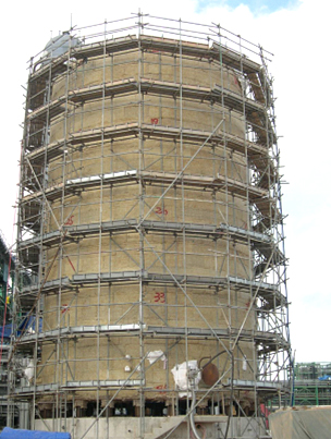
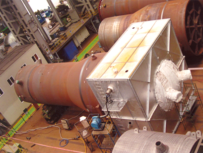
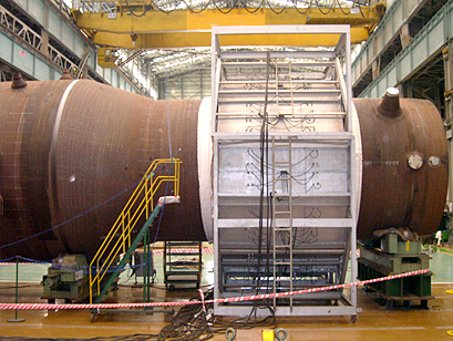
◎ Vessel Service
△ Gas Firing PWHT
△ Gas Firing PWHT

△ Gas Firing PWHT
△ Gas Firing PWHT

△ Gas Firing PWHT
◎ Plant Service
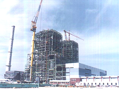
△ Gas Firing PWHT for the Main Unit at Nuclear Power Plant
△ Electric Resistance Heating type PWHT for the Main Unit at Nuclear Power Plant
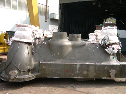
△ Electric Resistance Heating type PWHT for Casting material
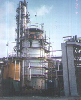
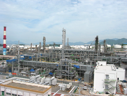
△ Gas firing PWHT for the Vessel at Petrochemical Plant
△ Heat Treatment for the Pipe at Oil Refinery Plant
△ Heat Treatment for the Pipe at Steam Power Plant
△ PWHT for the Electric Hearth at Steel Mill
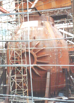
△ Electric Resistance Heating type PWHT for the Tuyere at Steel Mill
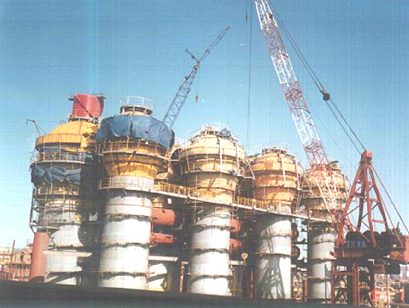
△ Gas firing PWHT for the Ball type Storage Tank

△ Gas Firing PWHT for the Storage Tank